
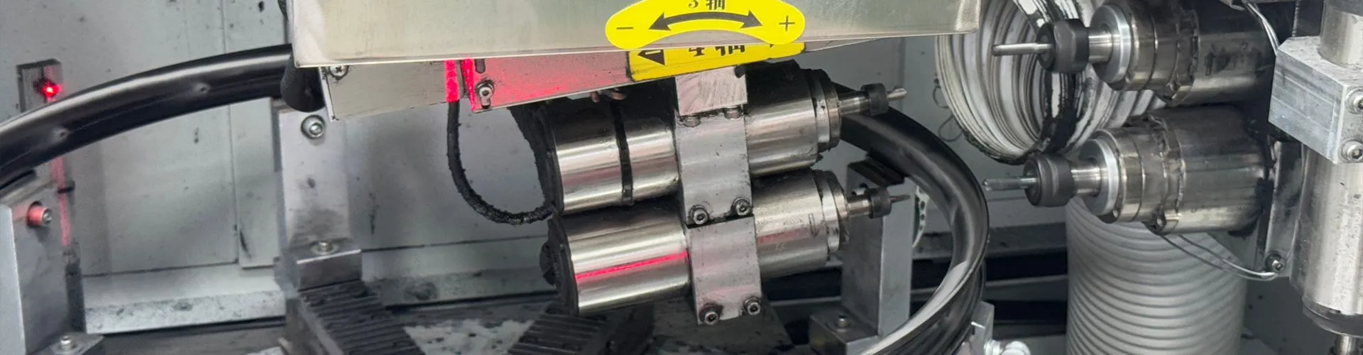
Drilling of spoke holes/drainage holes
1. Drilling Diameter: Continuously adjustable from 1.5 mm to 11 mm
Wide compatibility – Covers everything from ultra‑fine spoke holes (1.5 mm) to large rim valve holes and structural holes (11 mm) without changing the spindle or power head.
Stepless adjustment – High‑precision drill bushings and servo control allow fast switching to any intermediate diameter, reducing tool change time.
Material‑optimized cutting – Matching speed and feed strategies for aluminum alloy, carbon fiber composite rims, and steel rims ensures smooth hole walls and burr‑free results.
2. Drilling Angle: –11° to +11° bidirectional tilt
3D drilling capability – The spindle tilts in two directions within a vertical plane, meeting specific angle requirements for side‑mounted spoke holes, vent holes, and non‑vertical drainage holes.
Automatic positioning – Angle changes are driven by servo motors under CNC control, with a repeatability of ≤0.05° – no need for manual wedge blocks.
Combined operations – Drill vertical and angled holes in a single setup, eliminating secondary positioning errors.
3. Integrated spoke hole chamfering
One‑step process – Automatic coaxial chamfering (inner or outer) immediately after drilling, avoiding misalignment from a second tool change.
Programmable chamfer parameters – Chamfer depth and angle (45°, 60°, or custom) are CNC‑controlled to suit different spoke nipple shapes.
Surface quality – Sharp steel or PCD compound chamfering tools produce a burr‑free, vibration‑free finish, improving spoke assembly smoothness and fatigue life.
4. High‑efficiency drain hole drilling mode
Special canned cycle – A built‑in “drain hole drilling” macro optimizes pecking steps and chip‑clearing frequency, enabling high‑speed, low‑pressure drilling for water outlet holes in thin‑wall rims.
Anti‑deformation strategy – Minimum quantity lubrication (MQL) and stepped feed prevent internal ridge deformation caused by cutting heat or mechanical force.
Array drilling – Supports equally spaced, fixed‑pitch, or custom angular arrays – generate drain hole patterns with one command to improve water drainage.
5. Rim size compatibility: 20‑inch to 32‑inch (including road bike, MTB, e‑scooter, and some car spare rims)
Wide stepless adjustment – A sliding/rotating worktable fixture secures rims from small 20” to large 32” diameters without changing tooling.
Self‑centering system – Laser or probe‑assisted rim center finding ensures positional tolerance of hole patterns relative to the valve hole.
Offset hole compensation – For asymmetric rims (e.g., front fork offset designs), the software independently compensates radial offset per hole, guaranteeing perfect hole symmetry.
6. Ultra‑high precision: Repeatability ≤0.05 mm
Closed‑loop control – All linear and rotary axes are equipped with high‑resolution linear scales or magnetic encoders to eliminate leadscrew backlash and thermal expansion effects in real time.
What 0.05 mm means – On a 32‑inch rim circumference, a hole position deviation ≤0.05 mm makes spoke length errors negligible. When lacing the wheel, no spoke selection or grinding is needed; rim roundness and lateral runout can be held within 0.2 mm.
Process assurance – Automatic clamping force monitoring and vibration‑suppression algorithms prevent creeping or drifting, even when drilling large‑diameter or angled holes. First‑article quality is achieved from the start of production, with Cpk ≥1.33.
